Network computers “talk” to each other through a special language called network protocols. There are many different protocols, and each has its own task:
- Data transfer protocol, used to transport data between 2 computers.
- The data processing protocol is responsible for processing the data received from the data transfer protocol.
The IP protocol is a protocol of the network layer’s TCP / IP protocol stack. Everyone can read the article Learn basic TCP / IP model to know what is the function of the network layer! And today I will introduce more about the IP protocol. Let’s find out! 
Features of the IP protocol
- One of the most important protocols of the TPC / IP protocol suite.
- As a connectionless protocol: IP data is transmitted immediately if possible (best effort), without any connection establishment mechanism, no acknowledgment or flow control mechanism. Any IP is used, IP packets are not numbered when exchanging on the network …
- Each IP packet is handled independently of other IP packets.
- The IP protocol uses a hierarchical addressing mechanism, where the NetworkId part of the address is the same as the name of a road and the hostId part of the address will be the house number of a house on that path.
- There is no mechanism for recovering lost packets on the transmission line. This is passed on to the upper layer protocols to ensure reliability (TCP).
Packet structure
Including 2 parts is Header and data. The header contains the packet’s management information, data is the part of data to be transmitted encapsulated in an IP packet
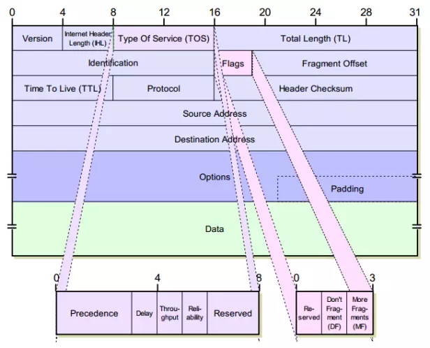
- VERS (4 bits) : Indicates the current version of the IP being used, If this field is different from the IP version of the receiving device, the receiving device will reject and discard these packets.
- HLEN (IP Header Length – 4 bits): indicates the header length of the datagram, in word units (32 bits). Without this field, the default length of the header is 5 words.
- Service Type (8 bits) : marking data for QoS tasks with IP packets
QoS (Quality of Service) is a set of techniques that allow the allocation of resources appropriately for different types of data, thereby ensuring network service quality for these data types.
- Precedence (3 bits) : indicates the priority to send datagram, specifically:
| Priority | Main |
|---|---|
| 111 | Network Control (highest) |
| 011 | flash |
| 110 | Internetwork Control |
| 010 | Immediate |
| 101 | CRITIC / ECP |
| 001 | Priority |
| 100 | Flas Override |
| 000 | Routine (lowest) |
- Delay (1 bit) : indicates the request delay. 0 : normal delay; 1 : low latency
- Throughput (1 bit) : Indicates the required throughput. 0 : normal throughput; 1 : high flux
- Reliability (1 bit) : only required reliability. 0 : normal reliability; 1 : high reliability
- Total Length (16 bits) : The length of the entire IP packet including the header is calculated in bytes. To know the length of the data, subtract the HLEN from the total length.
- Identification (16 bit) : Identifier field, along with other parameters such as source address (Source address) and destination address (Destination address) to uniquely identify each Datagram sent by a station. Usually the identifier is increased by 1 when a datagram is sent.
- Flags (3 bits) : Flags used while segmenting the datagram.
- Bit 0: reserved unused, the value is always 0.
- Bit 1: DF = 1 : The packet is fragmented, there is more than 1 segment, DF = 0 : The packet is not fragmented.
- Bit 2: MF = 0: the last paragraph, MF = 1 : not the last paragraph, there is another paragraph behind.
- Fragment Offset (13 bits): Indicates the position of the fragment in the IP Datagram in 64 Bit units.
- Time to Live (TTL) (8 bit) : used to prevent IP packet loops when routing errors occur on the network map. This value is set at the beginning of the packet sending and it decreases by 1 unit when passing through a router. When TTL = 0, the packet is discarded.
- Protocol (8 bit) : identifies which protocol is being transmitted in the data portion of an IP packet, such as TCP or UDP.
- Header checksum (8 bits) : checks the IP header for errors. If this check fails, the packet will be discarded at the location of the error.
- Source Address (32 bits) : the address of the source station.
- Destination Address (32 bits) : the address of the destination station.
- Option (with variable length) : allows adding new features to the IP protocol.
- Padding (variable length) : The structure of the IP packet specifies that the option must be a multiple of 32 bits, so if the option does not have enough bits, padding bits will be added to achieve this request.
- Data (variable length) : the data area is a multiple of 8 bits, maximum of 65535 bytes.
IP address
Every computer connected to the Internet has a unique address, which is the IP address. The goal is to uniquely identify any computer on the network.
Address structure
- The IP address consists of 32 binary bits, divided into 4 8-bit clusters (called octets). The octets are expressed as decimal and are separated by dots.
- The IP address is divided into two parts: the NetworkID part (the network address part) and the HostID part (the workstation address section).
 Figure 1
 - In 1 byte (8 bits), each value is assigned a value. If the bit is set to 0, it is assigned a value of 0, if the bit is set to 1, it can be converted into a decimal value. The lowest bit in the byte corresponds to 1, the highest bit corresponds to 128. So the maximum value of a byte is 255 corresponding to the case where all 8 bits are set to 1.
- For example, in Figure 1 , with the first octet and based on the calculation in the figure above we have: 10000011 = 128 + 0 + 0 + 0 + 0 + 0 + 2 + 1 = 131. Similar to the other 3 octets, we will produce an IP address of 131.108.122.204
- Note: NetworkID part bits are not allowed to be simultaneously 0 .
 Figure 1
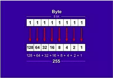
Types of addresses
- Network address (Network Address):
- Identifier for a network
- All HostID part bits are 0
- Broadcast address (Broadcast Address)
- Address to send data to all workstations in the network
- All HostID part bits are 1
- Workstation address (Unicast Address): assigned to a network port
- Group address (multicast address): identifier for group
Classes of addresses
The IP address space is divided into the following classes: 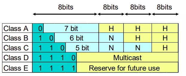
Class A
- Class A addresses use an early (8 bit) otet as the network part, the following three octets as the host
- The first bit of an A-class address is always kept as 0 .
- Network class A’s addresses include: 1.0.0.0 -> 126.0.0.0 .
- Network 127.0.0.0 is used as loopback
- The host part has 24 bits => every class A network has ( 2 ^ 24 – 2 ) hosts.
Class B
- Class B addresses use the first two octets as the network part, the second two octets as the host.
- The first two bits of a class B address are always kept as 1 0
- Class B network addresses include: 128.0.0.0 -> 191.255.0.0 . There are 2 ^ 14 = 16384 networks in class B.
- The host part is 16 bits long => a class B network has ( 2 ^ 16 – 2 = 65534 ) hosts.
Class C
- Class C addresses use the first three octets as the network part, the latter one as the host.
- The first three bits of a C-class address are always kept as 1 1 0 .
- Class C network addresses include: 192.0.0.0 -> 223.255.255.0 . There are 2 ^ 21 lives in class C.
- The host part is 8 bits long so there’s a C class network that has ( 28 – 2 = 254 ) hosts.
Class D
- The first four bits of a class D address are always kept as 1 1 1 0
- Including addresses in the range: 244.0.0.0 -> 239.255.255.255
- Used to make multicast address .
Class E
- The first five bits of an E class address are always kept as 1 1 1 1
- Addresses range from 240.0.0.0 onwards
- Used for backup purposes.
Attention:
- The IP address classes that can be used to host hosts are classes A, B, and C
- To easily identify an IP address of which class, we can observe the first octet of the address in the range:
| Class address | First octet of address |
|---|---|
| A | 1 -> 126 |
| B | 128 -> 191 |
| C | 192 -> 223 |
| D | 224 -> 239 |
| E | 240 -> 255 |
However, the hard division into classes (A, B, C, D, E) limits the use of the entire address space, leading to wasted address space. So what’s the solution  ? In part 2, I will talk more about how to solve this problem!
Thanks for reading 
Reference source : Computer network syllabus of Hanoi University of Science and Technology