This article is a continuation of the unfinished part of part 2 so I do not introduce anymore but go to the main problem 
3. Focus
Our eyes and the camera actually have a certain aperture size and therefore have to deal with issues that limit the depth of field: Only a certain range of subjects will be focused, and Everything outside this range will be blurred . Of course, our eyes can accommodate (focus) at different distances
Conflicts between accommodation and vergence occur in VR as well as in AR, as long as a stereoscopic screen with a fixed focal plane is used. However, for AR that see through optics with such stereoscopic rendering, there is another related problem: Not only will the virtual augmented parts be subject to conflict in the accommodation, but users will see the real world with the correct markers, meanwhile to see the virtual annotations in focus, users will need to adjust for the display image plane. Therefore, to read a text label that is almost positioned on the front plane of the building facade, the user must shift the focus back and forth between the building facade and the display image plane. Looking at the façade plane, users can see the architectural details are in focus, but the written explanation will be blurred, and vice versa. Any co-location of virtual and real objects will be affected from this problem, except the depth of the objects that will occur is in the display image plane. The severity of this problem has not been thoroughly evaluated. It still causes discomfort when used for a long time of use.
One possible solution to this problem is that the screen can shift the focus plane in real time. With such technology, one will need eye tracking to identify the objects that the user is focusing on and then adjust the focus plane displacement according to the user’s attention.
Multifocus displays Schowengerdt and Seibel 2012 offer another possibility to avoid vergence conflicts.
4.Occlusion
The separation between virtual and real objects is an important suggestion to convey the scene structure. Although precise matching between real objects is given naturally, and precise matching between virtual objects can be easily achieved by the z buffer, to achieve the correct combination. of virtual before real or vice versa, need special consideration. By using the z buffer, a video preview system can determine whether the virtual or real object is in the foreground, if there is a geometric representation of the actual scene. In optical see-through systems, where increments often appear as semi-transparent coatings, it is more difficult to make virtual objects appear as if they are actually in front of objects. real. There are three alternatives:
- Virtual objects can be displayed very bright compared to the intensity at which real objects are seen, so virtual objects will prevail. However, this can adversely affect the perception of the rest of the real scene.
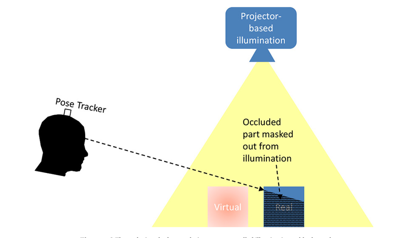
- In a controlled environment, the relevant part of the actual scene can be illuminated by a computer-controlled projector, while the rest of the scene (in particular real objects are obscured by virtual objects). remain in the dark and therefore unrecognizable. In these dark areas, virtual objects can be displayed and appear to hide real objects.
- An optical transparent screen can be enhanced with a liquid crystal display, allowing selectivity to make individual pixels transparent or translucent.
The ELMO HMD project has pioneered this approach

5.Resolution and Refresh Rate
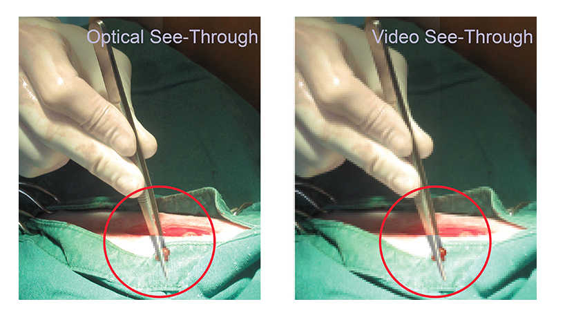
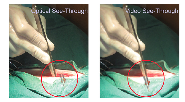
The resolution of the screen has an immediate impact on the fidelity of the image captured. In general, the resolution is limited by screen type and optical system. If a video-based solution is used, the resolution of the real world is further limited by the resolution of the camera. Typically, computer-generated screens will not match the maximum resolution that humans perceive directly in the real world. However, sufficient resolution is desirable to eliminate computer noise-induced artifacts that stand out from the user’s perception of the real world.
6. Field of View
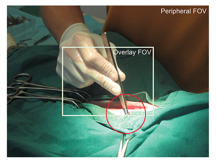
Field of View ( FOV ) is even more important than raw resolution . FOV and resolution are related, since more pixels are needed at the same density to fill a wider FOV. Wider FOV means that more information can be displayed to users in a view. In AR, it is distinguished between overlay FOV and peripheral FOV. In the FOV overlay, computer generated graphics are overlaid on the image of the real world. In contrast, peripheral FOV is composed of the natural, non-strengthening part of the visual medium. If the overall image in the image below has a FOV of 62 ° diagonally, the overlay FOV is marked as approximately 30 ° diagonally. Such a relatively narrow FOV means that users will often have to put a distance between them and virtual or real objects to see them fully, or move their heads in a sweeping motion to see the whole thing. scene over time. FOV limits are common in VR and especially AR displays.
In video-view AR, it is actually the camera’s FOV rather than the screen’s FOV that determines how much of the real-world information can be presented. Cameras usually have a larger FOV than the screen, so the camera image is actually compressed, similar to the fisheye effect. For example, when using a smartphone as a handheld AR magic lens: v, the camera on the back of the smartphone may have a FOV greater than the secondary angle of the screen.
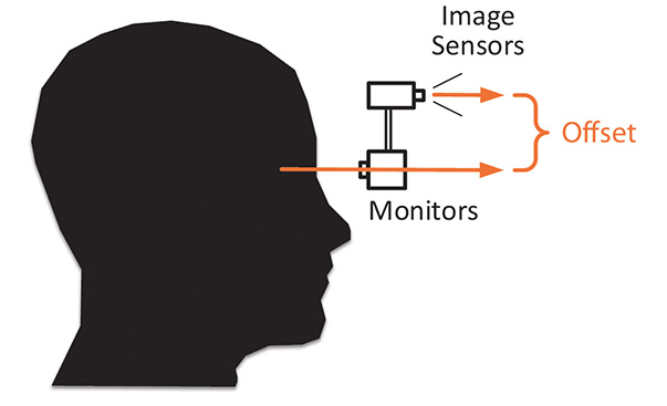
7.Viewpoint Offset
See-through monitors merge the virtual and virtual optical paths into one, so the resulting image is aligned to the design. This result is desirable, as it corresponds to natural viewing. However, it requires calibration of the virtual camera, which is used to create the virtual part of the AR screen, to the user’s eye. If the calibration is not done carefully, the compensation between the image parts will be the result. With the video preview screen, the camera frame can be used to register based on computer vision resulting in accurate pixel annotation.
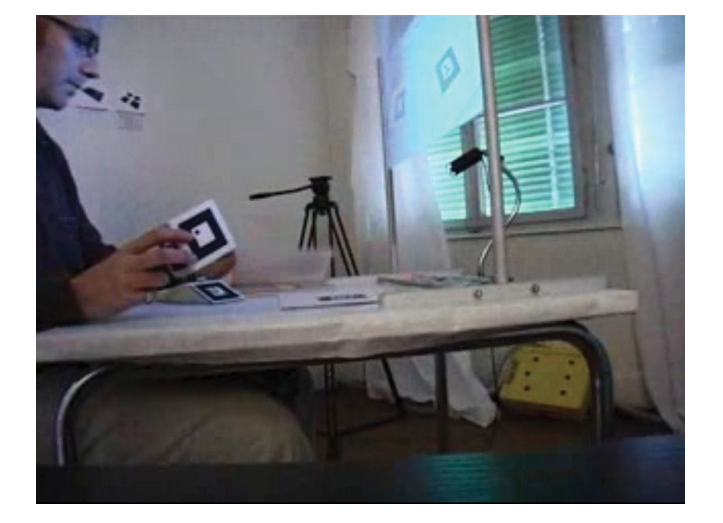
Video-watching profiles will often show a significant deviation between the camera’s viewing orientation and the viewing orientation of the screen where the camera image is displayed. This compensation may reflect restrictions in which the camera may be mounted (e.g. on HMD) or may be designed in AR workspace design. For example, a desk can display enhanced imagery from an overhead camera facing down on a vertical surface in front of the user, so that the space where the user sees real hands and an enhanced view.
8.Brightness and Contrast
Achieving adequate contrast in a see-through screen is generally difficult. Especially in outdoor situations or in situations with lots of natural light, most computer screens are not bright enough to achieve contrast. A common evasive measure is to reduce the amount of physical light that affects the viewing situation, for example, by using window blinds to control the influence of external light on projection in space or by manipulating An adjustable visor on HMD.
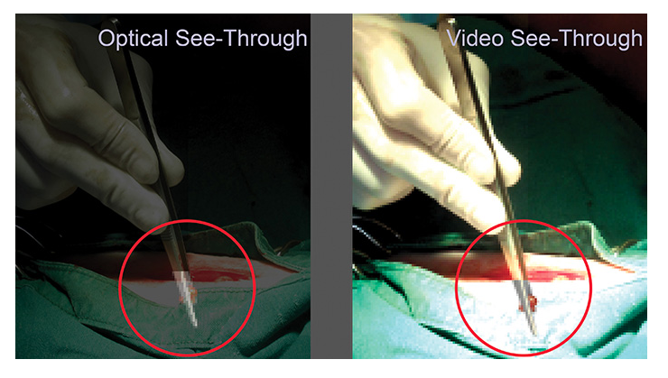
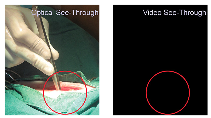
In VST , there is no need to directly observe the environment, so the amount of natural light in the visual environment can be controlled more easily. Unfortunately, the poorly achieved contrast of conventional video cameras becomes clearer. In addition, HMD VST usually only covers a certain part of the user’s field of view and natural light can come in from the periphery. In addition, VST depends heavily on operating electronic components. If the camera or monitor is not connected successfully, no meaningful images will be displayed
9.Distortions and Aberrations
Each specific screen, be it OST or VST, will involve optical elements, such as lenses. These optical elements can introduce distortions, such as the fisheye effect – in particular, if you want a wider field of view.
10.Latency
Temporary errors can have the same adverse effect as the space error. Just as inadequate spatial calibration can lead to deviations between virtual and real in the image, therefore, insufficient time-based coupling between virtual and real can cause spatial deviations. If the virtual elements in the AR display are displayed too late, perhaps due to the graphic creation taking too long to finish, the user may have moved during that time. Therefore, the virtual elements will be displayed in the wrong part of the image.
Latency affects both OST and VST, as virtual parts can be outdated in both cases. A potential advantage of VST over OST is the option of delaying the video so that it is suitable for virtual elements. The resulting AR screen will not deviate from space
Latency has been shown to contribute to the onset of cyberspace in VR and AR viewing scenarios. It is difficult to give absolute numbers, because the data from the various studies are very specific, but the more deeply studied thresholds are somewhere between 20 and 300 ms.