In the previous article, I introduced the Arduino, in this article I will guide you how to program the basic Arduino through the basic example: Make the LED light turn on and off automatically after a period of time. Let’s first begin to learn about the structure of an Arduino program.
Arduino program structure
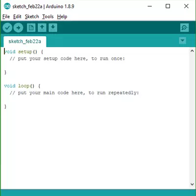
The initial structure of the program in Arduino IDE is quite simple, it only consists of two functions setup () and loop (). When the program starts to run, the commands in setup () will be processed first, we usually use this function to initialize the state and values of variables or parameters in the program.
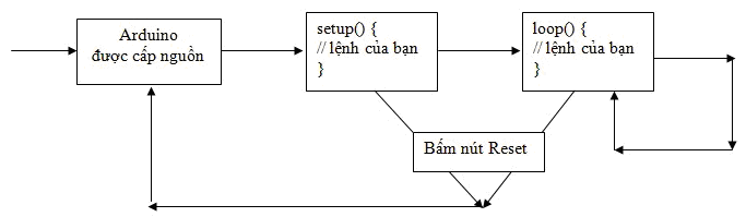
After setup () completes, the commands in loop () are run. This is an endless loop, so the lines of code in this function will be repeated continuously until you disconnect the power of the new Arduino board or intervene with the Reset button on the board, your program will return to the state it was in when the Arduino was newly powered, i.e. start running again from the setup () function.
This process you can see as shown below:
Next, we will try to program the Arduino through the basic example: Make the LEDs turn on and off automatically after a period of time, in order to do this example, we need to prepare some necessary hardware.
Create LEDs automatically turn on and off after a period of time
Hardware needed
- 1 Arduino Uno R3 includes a USB cable to the computer (It’s not really required to be this Arduino, you can replace it with any other Arduino series, but check its pinout)
- 01 any color LED light (on the market there is a 3mm or 5mm version, any version is fine, 5mm is brighter)
- 01 220 Ohm resistor
- Connection wire
Installation diagram
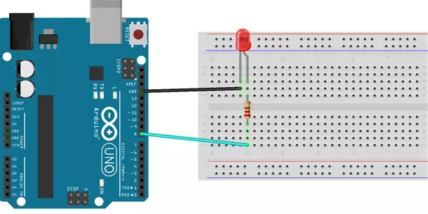
On the loop diagram placed on me, connect the negative pin of the LED door to the GND pin of the circuit (also known as grounding), the positive LED pin is connected to pin 8 through a resistor. Pay more attention to distinguish the positive and negative pins of the LED, as in the picture you will see that the positive leg is bent and the negative leg will be straight, but when you buy it, you will see the legs are straight, then the longer leg will be positive legs. With resistance, we don’t care about the positive and negative ends.
With the Arduino connection, here I use pin 8, you can use any other pin from 0 to 13, it makes no difference, only when we program.
After the connection is complete, you use the USB cable to connect the Arduino to the computer so we can load the code, (or if you like, load the code for the Arduino and then connect later, no problem)
Programming and code loading
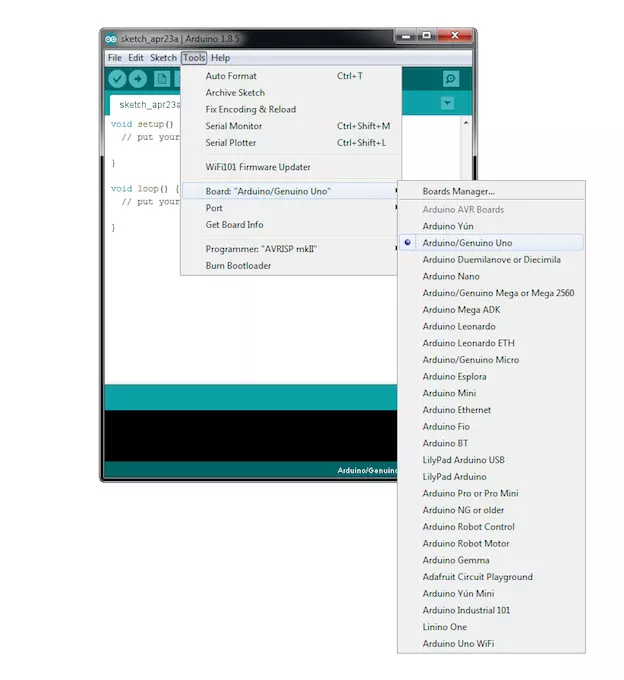
Before loading the code we need to check if the IDE is connected to the circuit or not, to do this go to Tools> Port and see if the COM port is correct Arduino or not.
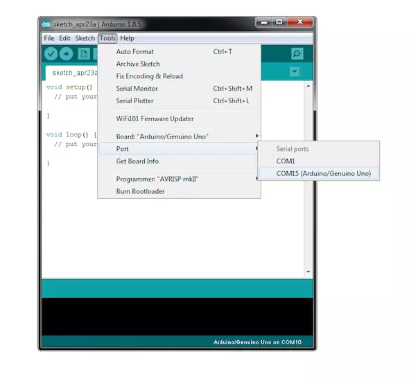
After checking the correct port, we need to tell the IDE what kind of Arduino board we are using, to do this go to Tools> Board and select “Arduino / Genuino Uno”.
Next we enter the following code:
1 2 3 4 5 6 7 8 9 10 11 12 13 | <span class="token keyword">int</span> led <span class="token operator">=</span> <span class="token number">8</span> <span class="token punctuation">;</span> <span class="token comment">//chân digital kết nối với LED thông qua trở</span> <span class="token keyword">void</span> <span class="token function">setup</span> <span class="token punctuation">(</span> <span class="token punctuation">)</span> <span class="token punctuation">{</span> <span class="token function">pinMode</span> <span class="token punctuation">(</span> led <span class="token punctuation">,</span> OUTPUT <span class="token punctuation">)</span> <span class="token punctuation">;</span> <span class="token punctuation">}</span> <span class="token keyword">void</span> <span class="token function">loop</span> <span class="token punctuation">(</span> <span class="token punctuation">)</span> <span class="token punctuation">{</span> <span class="token function">digitalWrite</span> <span class="token punctuation">(</span> led <span class="token punctuation">,</span> HIGH <span class="token punctuation">)</span> <span class="token punctuation">;</span> <span class="token function">delay</span> <span class="token punctuation">(</span> <span class="token number">1000</span> <span class="token punctuation">)</span> <span class="token punctuation">;</span> <span class="token function">digitalWrite</span> <span class="token punctuation">(</span> led <span class="token punctuation">,</span> LOW <span class="token punctuation">)</span> <span class="token punctuation">;</span> <span class="token function">delay</span> <span class="token punctuation">(</span> <span class="token number">1000</span> <span class="token punctuation">)</span> <span class="token punctuation">;</span> <span class="token punctuation">}</span> |
Explain:
- In the setup function we initialize the state of the pin through pinMode (), there are 2 basic modes OUTPUT and INPUT, with OUTPUT is to output control signals (like control LED turns on and off in this post), and INPUT is reading the external value (I will introduce in another article later).
- In the loop function we have the digitalWrite function, this is the function to set the control state for the digital pins, there are 2 states HIGH (or input value 1 is fine) and LOW (value 0), where HIGH is on LED, LOW turn the LED off, and the delay function causes the program to stop running for a period of ms, helping us to keep the current LED state before going to a new state.
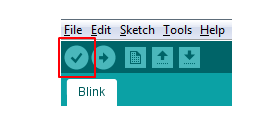
Now we will need to compile the code before loading the code for the circuit. The Arduino is a small circuit that can only read machine code, but the code written in the IDE is in C language. Therefore, in order for the Arduino to understand C commands, we have to convert them into machine code, this process is called translate. To compile the code, click the “Verify” button shown below:
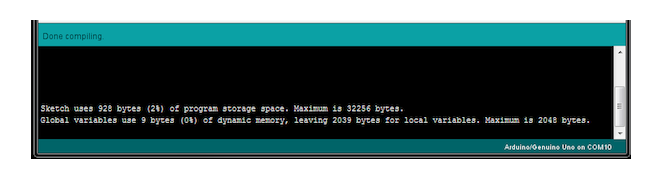
Once the IDE has finished compiling, you should see a result in the output window at the bottom of the IDE. The output window is useful for viewing successes, errors, warnings, and memory usage information:
The final step is to load the code, to do this click on the “Upload” button, which is the arrow to the right of the “Verify” button.
The Arduino’s onboard LED will now blink as you load the code, enjoy the results after loading the code!
So I have completed the basic programming with the Auto Led example, in the following articles I will continue to introduce other Arduino projects so that you can program Arduino more proficiently.
See you again.